

In accordance with the task of Activity 3.2 of the project, a demonstration solar power plant (SPP) was installed and comissioned. This SPP is designed to compensate for its own electricity consumption and demonstrate the capabilities of renewable (solar) energy equipment to save energy.
The mounted SPP is located in an accessible place - the laboratory of physical bases of renewable energy sources of the Department of Energy Management and Technical Diagnostics of IFNTUOG. Structurally, SPP is built according to the network scheme and consists of an array of photovoltaic panels, a grid tie inverter and a smart meter through which it is connected to the electrical grid (Fig. 1).
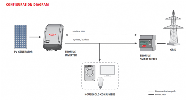
Figure 1 - Block diagram of a demonstration solar power plant
This SPP converts DC voltage from an array of photovoltaic panels into a variable, which is fed into the network, thus compensating for its own power consumption. A smart meter that is connected by a data line to a grid tie inverter allows you to implement and demonstrate various scenarios of SPP operation and to account for electricity consumed after the smart meter. A possible scenario is when all the energy generated during the day is transmitted to the grid and a possible scenario is when by controlling the power of the grid tie inverter the energy generated from solar radiation compensates for consumption after the smart meter but the flow (export) of energy to the grid does not occur (scenario 0% Feed in Mode ).
As mentioned above, the SPP equipment is a laboratory of physical bases of renewable energy sources of the Department of Energy Management and Technical Diagnostics of IFNTUOG, namely a grid tie шnverter (3 kW), DC voltage switchboard with protection and switching devices and AC voltage switchboard through which it is connected to the grid (Fig. 2) Array of photovoltaic panels with a total power of 3420 W (array power is selected higher than the power of grid tie inverter to compensate for the drop in performance of photovoltaic panels during heating), consisting of 12 photovoltaic panels located on the roof of the adjacent building. The DC voltage from the array of photovoltaic batteries is supplied to the grid tie inverter via an overhead line (Fig. 3).
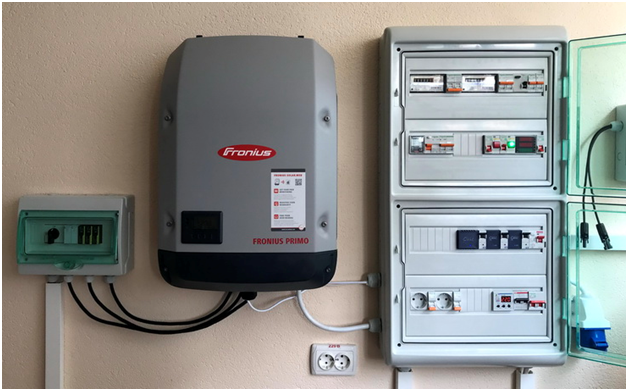
Figure 2 - Grid tie inverter and DC and AC switchboards of a demonstration solar power plant
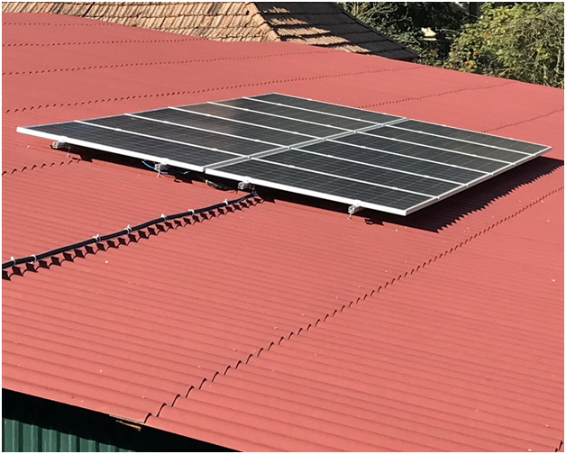
Figure 3 - Array of photovoltaic panels of a demonstration solar power plant
Display and demonstration of the demonstration SPP is carried out on the screen of the grid tie inverter (Fig. 4) and using the web application Fronius Solar web (Fig. 5).
In addition to the smart meter, which is located on the AC voltage switchboard, smart-MAC energy monitors are used to monitor power consumption and operation of SPP in compensation mode - for direct measurement of total consumption, D103 smart-MAC energy monitor with circuit current transformers is used for SPP generation; to determine the consumption of electricity by the main consumers after the switchboard, which are electric boiler and lighting system of common areas of the department, universal energy monitors D105 smart-MAC are used, which are connected to the telemetry pulse outputs of electromechanical meters placed in the switchboard (Fig. 6).
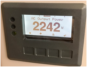
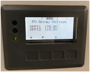
Figure 4 - Display and demonstration of the demonstration SPP on the screen of the grid tie inverter
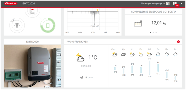
Figure 5 - Display and demonstration of the demonstration SPP in the web application Fronius Solar web
To display the work of the demonstration SPP, a page was created in the web application of the energy monitoring system for the university building (Fig. 7).
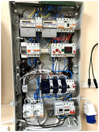
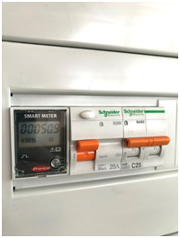
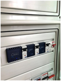
Figure 6 - AC switchboard of the demonstration SPP with installed means of monitoring and accounting of electricity (Fronius smart meter, smart-MAC energy monitors and electromechanical meters)
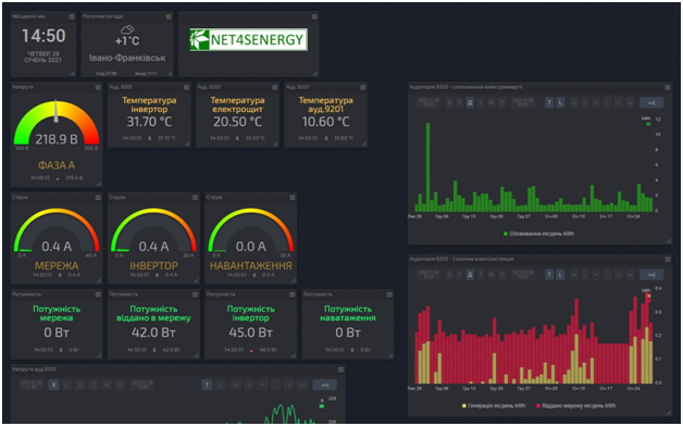
Figure 7 – To display SPP operation we created a page in the web application of the energy monitoring system for the university building